 |
EnigmaIOT
0.9.8
Secure sensor and gateway platform based on ESP8266 and ESP32
|
|
EnigmaIOT
0.9.8
Secure sensor and gateway platform based on ESP8266 and ESP32
|
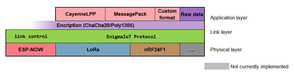
System functions are divided in three layers: application, link and physical layer.
The named EnigmaIoT protocol is designed to use encrypted communication without the need to hardcode the key. It uses Elliptic Curves Diffie Hellman algorithm to calculate a shared key.
The process starts with node announcing itself with a Client Hello message. It tells the gateway its intention to establish a new shared key. It sends public key to be used on gateway to calculate the shared key.
Gateway answers with Server Hello message that includes its public key for shared key calculation on node.
Once shared key is calculated, node send an encrypted message as Key Exchange Finished message. Poly1305 encryption tag is used to check message integrity.
If gateway validates tag correctly it answers with a Cipher Finished message.
This process is protected with a 32 byte shared network key, used for authentication. As in the first two messages shared key is not known yet, Client Hello and Server Hello messages are encrypted whit this network key. If network key is not the same on gateway and node this will lead to decryption errors and messages will be ignored.
In case of any error on node key negotiation gateway sends an Invalidate Key to reset to original status and forgets any calculated shared key for this node.
When key is marked as valid node may start sending sensor data.
Optionally, gateway can send data to node. As node may be sleeping between communications, downlink messages has to be sent just after uplink data. So, one downlink message is queued until node communicates. Node waits some milliseconds before sleep for downlink data.
If a new downlink message arrives, old scheduled data for that node, if any, is overwritten.
In case of nodes that do not sleep (like a mains powered relay), gateway can send downlink data in any moment. Sleepy node is signaled during node registration on a bit in Key Exchange Finished message. It is set to 1 to signal that node will sleep just after sending data.
Key is forced to change every period. Gateway decides the moment to invalidate each node key. If so, it sends an invalidate key as downlink, after next data message communication. This key validity period is configurable on EnigmaIoTconfig.h file.
After that node may start new key agreement sending a new Client Hello message.
All nodes and gateway are identified by its MAC address. No name is assigned so no configuration is needed on node. Function assignment has to be done at a higher level.


Client hello is sent by node to start registration procedure. It includes the public key to be used on Elliptic Curve Diffie Hellman (EDCH) algorithm to calculate the key. Initialization vector (IV) is used for encryption. There is a random 4 byte field reserved for future use.
This message is sent encrypted with network key.

After receiving and checking Client Hello message, gateway responds with a Server Hello message. It carries gateway's public key to let node calculate key using ECDH. There is a random 4 byte field reserved for future use. Gateway assigns node a NodeID. It is signaled as a 2 byte field.
Server Hello message is sent encrypted with network key.

Node data is always encrypted using shared key and IV. Apart from payload this message includes node ID and a counter used by gateway to check lost or repeated messages from that node.
Total message length (without tag) is included on a 2 byte field.

In case that extreme performance is needed there is the possibility to send unencrypted data so processor spends a few milliseconds less. It is not recommended to do so unless you want to investigate crypto software performance. Use at your own data risk :D
This message also includes node ID and a counter used by gateway to check lost or repeated messages from that node.

Gateway can send commands to an individual node in a similar way as sensor data is sent by nodes. For nodes that can be slept between consecutive data messages this commands are queued and sent just after a data message is received.
Only last message is queued. In case Gateway tries to send a new message, old one gets deleted and overridden by the new one.
Possible values of first byte means:
02: SET command (unicast)
82: SET command (broadcast)
12: GET command (unicast)
92: GET command (broadcast)

Broadcast messages of this type start with 0x84.

Gateway and node can exchange internal control commands. These are used to set internal protocol parameters like sleep time. This type of messages are processed like normal downlink messages, but are not passed to higher level (user code) in Node.
Some control messages, like OTA update messages, require that they are processed immediately. Hence, it is required that node is not in deep sleep mode. This can be controlled, for instance, using another control command to set sleep time to 0.


In non sleepy nodes, it may be useful to send a message from time to time to let Gateway know that node is still active and let Node to check that is is still registered in Gateway.
Clock syncronization may be a very good feature if you need to coordinate actions on different nodes.
EnigmaIOT combines these two features into one request and response. Nodes may send clock sync request every some time to ping gateway and get common clock updated. Clock synchronization uses a mechanism similar to the one used by SNTP protocol.
Notice that this is not world time sync but a numeric clock.
Since version 0.9.2, if Gateway has its internal time synchronized using NTP it sends non sleepy nodes current real date and time in millisecond Unix format .
This feature may be disabled if needed.


In order to make node messages more readable for humans, this implements a way to let Gateway to translate EnigmaIOT addresses to custom names (for instance, "RoomBlindControl"). This eases node replacement in case of failure.
Node names can be up to 32 characters long and should avoid characters different of letters and numbers. Characters #,+ and / are specially forbidden.
Node name is configured by user during first configuration in WiFi Web portal.

After every data message from nodes, gateway evaluates key integrity and validity. In case of any error decoding the packet gateways ignores data and reply with this message indicating the reason that caused error. Node must start a new registration procedure in order to send data again. After this new registration node resends the last data message.
A gateway defines a key validity period after that a node key is marked as expired. In a message is received after that is processed normally but an Invalidate Key message indicating key expiration as reason. Node then starts a registration procedure but does not retry communication.
Invalidate Key message is always sent unencrypted.


A gateway concentrates communication from all nodes, manages their registrations status, negotiate session key with them and outputs their messages to an output protocol.
EnigmaIOT MQTT Gateway is the implementation for a MQTT gateway.
Since version 0.7.0 Gateway is a ESP32 or ESP8266 board with 4 MB of flash memory or more. ESP8266 gateways cannot use MQTT TLS encryption due to memory limitations.
Use of ESP32 platform is recommended. ESP8266 EnigmaIOT gateway code is less tested.
Thanks to modular design, other output modules may be easily developed by implementing GwOutput_generic.h. Examples of this may be LoRaWAN output gateway, COAP gateway or any other network protocol that is needed. Even an offline SD data logger could be done.
I've included a Gateway with dummy output module to show simple OutputGw module development.
In order to configure you need at least this data:
User code may add additional custom parameters.
A node is either a ESP8266 or ESP32 board with a number of sensors. A node may sleep between sensor readings, status is stored so that it may send data without reconnection.
Any ESP8266 or ESP32 board with at least 1 MB of flash may be used.
There are several implementations in examples:
EnigmaIOT Node: Basic node with deep sleep function. Sensor data is mocked up in example and sent using CayenneLPP encoding, you only need to replace it with your sensor reading code. Expected duration with 2 AA type batteries is more than one year, but a low power booster/regulator should be used in a custom board.
Enigmaiot Node MsgPack: It has same functionality as the example above but uses JSON and MessagePack as Payload encoding.
EnigmaIOT Node NonSleepy: Same functionality as previous examples but this does not sleep. This may be useful for sensors or actuators which are connected to mains, like light switches or smart plugs.
EnigmaIOT LED Flasher: On non sleepy nodes a common clock may be synchronized with gateway. This is an example of this. All nodes that include this firmware will flash their built in LED synchronously after successful registration.
For configuration, node needs this data:
User code may add additional custom parameters.
Although it is not mandatory at all, use of CayenneLPP format is recommended for sensor data compactness.
You may use CayenneLPP library for encoding on node and decoding on Gateway.
Example gateway code expands data message to JSON data, to be used easily as payload on a MQTT publish message to a broker. For JSON generation ArduinoJSON library is required.
In any case you can use your own format or even raw unencoded data. Take care of maximum message length that communications layer uses. For ESP-NOW, maximum payload length it is 217 bytes.
Since version 0.9 payload encoding is signaled on user data messages (both uplink and downlink) so new formats are possible. Currently CayenneLPP and MessagePack formats, in addition to RAW data, are possible. Check examples for usage instruction. MessagePack encoding and decoding are managed by ArduinoJSON library.
This change may produce incompatibilities with older versions so make sure you update your gateway and all your nodes to latest library version.
Gateway has always its WiFi interface working as an AP. Its name corresponds to configured Network Name.
During first start, after connecting supply, node tries to search for a WiFi AP with that name. Whet it is found, node will use its MAC address and channel as destination for ESP-NOW messages. It also gets RSSI (signal level) and reports it to gateway.
This information is stored in flash so node will use it to communicate in all following messages.
In the case that gateway has changed its channel (for instance due to a reconfiguration) node will not be able to communicate again.
If several (2 by default) transmission errors are detected by node, it starts searching for gateway again. When found it keeps sending messages normally and new channel is updated in configuration persistently.
So, node will always follow the channel configuration that gateway is working in.
A user may program their own output format modifying gateway example program. For my use case gateway outputs MQTT messages in this format:
A prefix is configured on gateway to allow several sensor networks to coexist in the same subnet. After that address and data are sent.
After every received message, gateway detects if any packet has been lost before and reports it using MQTT message using this format:
EnigmaIoT allows sending messages from gateway to nodes. In my implementation I use MQTT to trigger downlink messages too.
To make it simpler, downlink messages use the same structure than uplink.
Node address means destination node address. Configurable prefix is the same used for uplink communication.
Commands may be given in JSON format. In that case they are sent to node in MessagePack format. That makes that mode gets the complete JSON object. This implies that no change is needed on Gateway to add new node types. Gateway is transparent to user data.
This is an example of MQTT message that triggers a downlink packet.
If node uses a name, MQTT message may use of it.
After sending that command node will receive a 'set' command with data {"light1": 1, "light2": 0}.
Commands can be sent in any other format different that JSON, even binary. In that case they are sent without conversion to node using MessagePack encoding format to reduce transferred data bits.
Control messages are intended to set node specific settings, like sleep time, channel, trigger OTA update, etc. They are not passed to the main node sketch but gateway treat them as normal downlink messages.
Normally control commands trigger a response as an uplink message.
This is the list of currently implemented control commands:
| Command | Response | |
|---|---|---|
| Get version | <configurable prefix>/<node address | node name>/get/version | <configurable prefix>/<node address | node name>/result/version {"version":"<version>"} |
| Get sleep duration | <configurable prefix>/<node address | node name>/get/sleeptime | <configurable prefix>/<node address | node name>/result/sleeptime {"sleeptime":"<sleep_time>"}" |
| Set sleep duration | <configurable prefix>/<node address | node name>/set/sleeptime <sleep_time> | <configurable prefix>/<node address | node name>/result/sleeptime {"sleeptime":"<sleep_time>"} |
| OTA message | <configurable prefix>/<node address | node name>/set/ota <ota message> | <configurable prefix>/<node address | node name>/result/ota {"result":"<ota_result_text>,"status":"<ota_result_code>"} |
| Identify node | <configurable prefix>/<node address | node name>/set/identify | None |
| Reset node configuration | <configurable prefix>/<node address | node name>/set/reset | <configurable prefix>/<node address | node name>/result/reset {} |
| Request measure RSSI | <configurable prefix>/<node address | node name>/get/rssi | <configurable prefix>/<node address | node name>/result/rssi {"rssi":<RSSI>,"channel":<WiFi channel>} |
| Request node name | <configurable prefix>/<node address | node name>/get/name | <configurable prefix>/<node address | node name>/result/name {"address":<node address>,"name":<Node name>} |
| Set node name | <configurable prefix>/<node address | node name>/set/name <Node name> | <configurable prefix>/<node address | node name>/result/name {"address":<node address>,"name":<Node name>} |
| Restart Node MCU | <configurable prefix>/<node address | node name>/set/restart | None |
For instance, publishing enigmaiot/12:34:56:78:90:12/get/version will produce enigmaiot/12:34:56:78:90:12/result/version 0.2.0.
Messages are encoded to reduce the amount of bytes to be sent over internal protocol, so that the air time is as short as possible.
| Command | Msg type | Encoding |
|---|---|---|
| Get version | 0x01 | None |
| Version result | 0x81 | version as ASCII string |
| Get sleep time | 0x02 | None |
| Set sleep time | 0x03 | Sleep time in seconds (Unsigned integer - 32 bit) |
| Sleep time result | 0x82 | Sleep time in seconds (Unsigned integer - 32 bit) |
| OTA Update | 0xEF | OTA update specific format |
| OTA Update result | 0xFF | OTA result code (text and integer code) |
| Identify | 0x04 | None. Function to identify a physical node by flashing its LED |
| Reset node configuration | 0x05 | None. This will set node to factory config |
| Reset config confirmation | 0x85 | None |
| Request measure RSSI | 0x06 | None |
| Report measure RSSI | 0x86 | RSSI (signed integer - 8 bit), WiFi channel (unsigned integer - 8 bit) |
| Get node name | 0x07 | None |
| Report node name | 0x87 | Node name as string |
| Set node name | 0x08 | Node name as string |
| Restart node MCU | 0x09 | None |
| Send Broadcast Key | 0x10 | 32 byte key |
MQTT Gateway example includes plain Arduino OTA mechanism. OTA is protected using network key selected during initial configuration.
On nodes, OTA updates are transferred using the same mechanism. Firmware is sent over MQTT using a Python script. Then gateway selects the appropriate node and send this binary data over ESP-NOW.
As ESP-NOW restricts maximum payload to 250 bytes per message firmware is splitted in chunks. Every chunk is 212 bytes long, so that it fits together with message headers and is multiple of 4. This splitting work is done by EnigmaIoTUpdate.py script.
A requirement is to have installed Python3 in the computer used to do the update.
In order to run the update, you need to install paho-mqtt library. To do that you can follow instructions here.
An example of this command could be like this:
Notice that using ESP-NOW, device address correspond to MAC address of your ESP8266 or ESP32 node.
It is very important to configure user and password on you MQTT broker. Besides, if it is going to be accessed from the Internet you should activate TLS encryption and a certificate.
JSON controller examples have integrated Home Assistant autoconfiguration. So, it is possible to design a node that autoregister automatically as soon it is connected to EnigmaIOT network.
You just need to add the specfic header files that correspond with your node profile. Currently these are implemented:
Additionaly you need to add specific configuration in separate methods like this from SmartSwitchController.cpp
Finally you need to register every auto discovery methods in connectInform method.